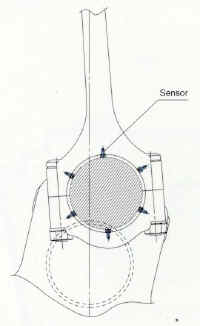
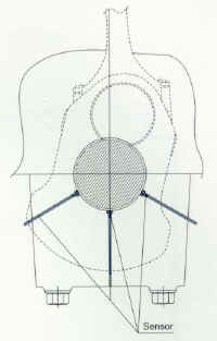
Example | Piston Behavior Measurement | Piston Ring Behavior Measurement |
---|---|---|
Installation Diagram | ||
Purpose of Measurement | Sensors are embedded in the connecting rod bearing, and the gaps between the crankpin and sensors are measured to evaluate the locus of crankpin centers. | Sensors are attached to the main bearing of the crank journal to measure movement and gap. |
Specifications | Operating Temperature: Max
180°C
Measuring Range: Dependent on installation geometry, please contact us for assistance. *These are reference specifications. If your operating conditions require different specifications, contact AEC. We may have the sensor you need or would be pleased to manufacture a sensor to meet your requirements. |
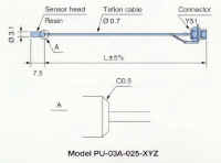
Operating Temperature: Max
180°C
Measuring Range: Dependent on installation geometry, please contact us for assistance. *These are reference specifications. If your operating conditions require different specifications, contact AEC. We may have the sensor you need or would be pleased to manufacture a sensor to meet your requirements. |
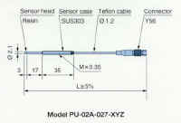
Remarks | The measurement range varies depending on sensor selection which depends on connecting rod size. For example, if the PU-03A probe is used, the measurement range (linear output) will be 0-500mm with 6 x 6mm diameter drilled holes. | The measurement range varies depending on sensor selection which depends on crankshaft journal size. |
Sensor |